|
-
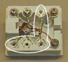
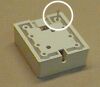
- Tighten screws #1 & 2 securely.
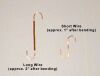
- Using the needle-nose pliers, place opposite bends in the ends of the long piece of hookup wire, so that the wire forms an elongated "S" shape.
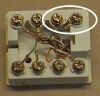
- Place the bent piece of hookup wire under the heads of screws #3 & 6 as shown, being careful not to dislodge the jack connector leads already under the screw heads.
- Tighten screws #3 & 6 securely.
- Examine your work carefully, making certain that none of the jack connector leads are in contact with each other, nor with the newly-added wires.
- Replace the cover on this jack terminal block.
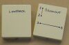
- Using a permanent marker, label the assembled jack with the legend LOOPBACK.
- Locate the jack terminal block set aside in Step #4 and remove screws #1, 2, 3, & 6.
- Locate the cover for this jack terminal block and install it onto the block.
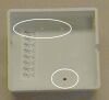
- Turn the assembled jack upside-down on the bench.
- Using the finishing nail, and inserting it through each open screw hole in turn, mark the cover in line with the screw locations by tapping on the head of the nail. These marks will become drill centers for Step #20.
- Remove the cover from the jack terminal block.
- Using the drill motor and the 5/64" twist drill, carefully drill through the cover in each of the four locations marked.
- Reinstall the four screws removed in Step #15, being careful to secure each of the jack connector leads under its correct screw head. Tighten the screws securely.
- Replace the cover on this jack terminal block.
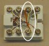
- Using the permanent marker, label each of the four holes in the cover with the numbers 1, 2, 3, & 6 as shown.
- Draw connecting lines on the cover between holes #1 & 2, and between holes #3 & 6.
- Label the assembled jack with the legend BREAKOUT.
- The assembly steps are now completed!
Using the Tester
Using the tester is simplicity itself, and all testing can be done with the suspect cables in place. There is no need to remove any so-installed cables from conduits for testing. Start out by inserting one end of the suspect cable into the jack in the loopback unit. Then go to the other end of the cable and insert it into the jack in the breakout unit. Now, working at the breakout unit, set your multimeter for continuity testing. Next, insert one lead of the meter into hole #1 and the other into hole #2, being sure to insert the test leads until they come into contact with the screw heads in the terminal block. The meter should indicate continuity between these two points. Repeat the process using holes #3 and #6. Again, the meter should indicate continuity. If both of these test show continuity to exist, the cable is intact and should be usable. Any lack of continuity in the above tests indicates a faulty cable. Testing procedures are the same for straight-through and crossover cables.
Occasionally, you may wish to determine whether a particular cable is a straight-through cable or a crossover cable. This can usually be done through careful examination of the wire sequences in the RJ-45 connectors at the opposite ends of the cable. Sometimes though, the cable will have opaque connectors or connector boots, making it difficult to see the wire colors within. This determination is very easily made using two breakout units. Note that this particular procedure does require removal of installed cables, as you must access both ends at once with your
multimeter. It also requires that you prepare a second breakout unit as described in Steps 15 through 25 above. Simply connect one breakout unit to each end of the cable and check for continuity between both holes #1 of each breakout unit. If there is continuity from hole #1 to hole #1 of the opposite unit, the cable is a straight-through cable. If there is no continuity shown in that test, check between hole #1 of one unit and hole #3 of the other. Continuity there indicates that the cable is a crossover
cable.
Page 1: Make a low
cost LAN cable tester
Page 2: Procedure for building network
cable tester (this page)
- ChrisP -
|
|